Site layouts, cad drawings, blocks and visualisations
coopergeomatics site layout crane block

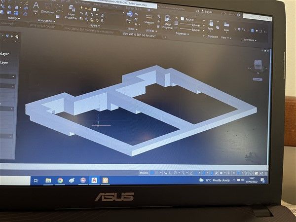
I am proficient with autoCAD and over the last 10 years have acquired or developed numerous lisps, macros, shortcuts and blocks to make my cad time more efficient and productive.  I wouldnt say I am an expert at CAD but I would say I am an expert at the bits of CAD that are relevant to me!!

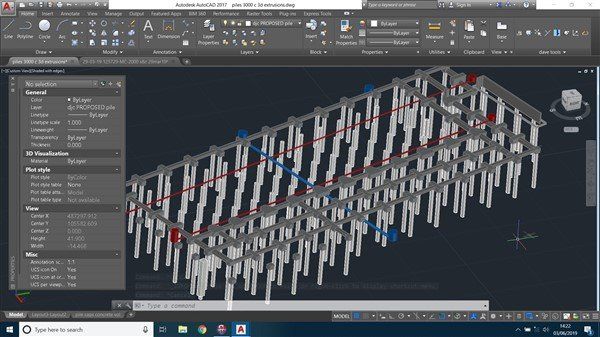
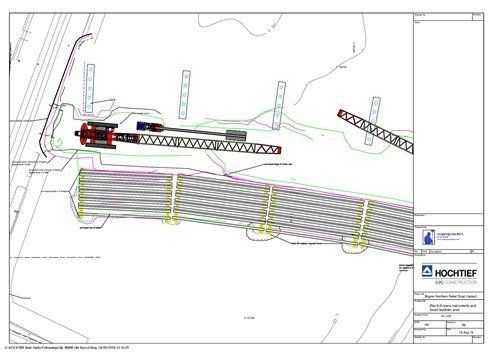
I have a vast array of CAD blocks that add a bit of realism and scale to cad drawings. When managers find out i am skilled in autoCAD and the blocks i am asked to do all sorts of drawings - which makes my life easier. The image alongside is a good example of this. Hochtief needed to create a laydown area for the precast bridge beams. The solution i came up with was to create blocks of the precast beams, the crane,  and the sleepers that the beams would rest on. I surveyed the area available placed the blocks on the drawing and obtained coordinates for the sleepers and then set them out. It all fitted - of course it did!


Plot foundations

These plot founds didnt have levels, just a FFL with tree influence depths and was a bit confusing. By drawing them in 3d I could see what was going on and also calculate the concrete volumes. I also created the machine control files for the dig as well.


3d clash detection

cooper geomatics autocad

2d drawings only show half the story. Using autocad 2017 I extruded the items and created a 3d view of the relationship between the the piles, the foundations and the drainage - then it all becomes clear. We need to move the drainage!!


Visualisation
coopergeomatics new roundabout chichester

The image opposite is a good example of this. These are the central kerbs on a new roundabout. Everyone who saw these kerbs, from passers by to our own people and the highways inspector thought i'd got this wrong. "It doesnt look right", "We never approved this!", "the engineer must have set it out wrong!" No the engineer is correct. The designer knew it was correct  but people look at a drawing and build up a picture  of what they think it should be. We humans struggle to see 3d shapes on 2d bits of paper.  When I pointed out there is a 600mm level difference between the high and low points, and the surrounding kerbs went in could people see that it was correct!!


This is a 3d view of the same roundabout. I used LSS to create this from the designers information and you can see it isnt flat!!! When its finished I'll post the as built.


I had it on another job, a large car park. The Client thought they were getting a flat car park as they were only given a fancy 2d cgi, but it was shaped and terraced to allow surface water run off, so when we built it obviously "it was wrong", "wasnt expecting this", "the engineer has f@cked it up ". A 3d cgi would have shown the falls.


So by creating a 3d visualisation or a simple cross section you can see......before it gets built and manage expectations.

Now the trief kerbs are in and base and binder is on it doesnt look odd now!

Now the surface course, white lines and signs are in it looks normal!


Cad blocks
Its not until you put scaled blocks onto the cad drawing that you can see if they fit. How many times has the designer used a couple of lines to identify something that is actually bigger than they thought and just doesnt fit. My personal favourite is a line behind a kerb which indicates a duct route and they refer to a trench type....that needs 3 ducts.....at least 500 width...and you need to be able to get streetlights in.....and tree pits!!.......and not to mention the kerb and haunching.

I also like the 2m footpath that needs to have bt, water, gas, LV and HV and future comms in which need to be a specific distance and depth apart. Then you introduce a jb106 BT box....behind the kerb and the effective width reduces significantly.